Raspbery Pi B+ IDE cable connection
GPIO extension board
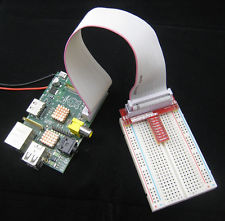
Wanting to play with electronic circuits an Raspberry PI seemed like a good choice to by. And of course you get the most powerful version (B+), an breadboard and a GPIO connector plug for it. Awesome you’re good to go… or are you? The setup bought was almost the one on the picture to the right. With one tiny exception, the newest version of Raspberry Pi has 40 pins whereas the older versions has only 26, and of course the plug does not fit. Good new is the first 26 pins are the same on the B+ as it’s predecessor, so home made solutions is an option 
Of course in such a case Google is your friend and inspired by the post Raspberry Pi GPIO Expansion Cable from a Used IDE Cable provided a source of inspiration, for creating an home made connector cable. Most important detail from Tom Hardgrave’s (not sure if he’s the original author, as he links to an original post without an author  )post is noting this part:

The IDE cable fits the Pi B+
Fortunately 40 pin IDE cables is quite easy to get your hands on. Most old work station computers (more than 5 years old) will have one of those to connect hard drives and DVD/CD-rom drives. And the 40 pin cable fits perfectly. Into the GPIO port of the Pi B+, so there’s no need for extra work in the PI-end of the setup. On the breadboard end we’re a little less fortunate.
The cable doesn’t fit the connector
Here the connector of course is built for the 26-pin connector of the older Pi models. So the basic course of action was to simply cut off one end of the IDE cable, and remove one of the connectors of the 26-pin cable. This can be done with a screw driver and a bit of force – be careful though not to break the “knives” for connecting to the wires inside the cable. When you got the cable cut at one end (keeping one 40-pin connector for connecting to the Pi) and the 26 pin connector from the other cable you need to figure how to turn cable in the Pi. Once you decided on a way to face it – a good choice might be having the end marked on the cable turn towards the 26 connectors you’ll be using – it’s time to actually connect it.
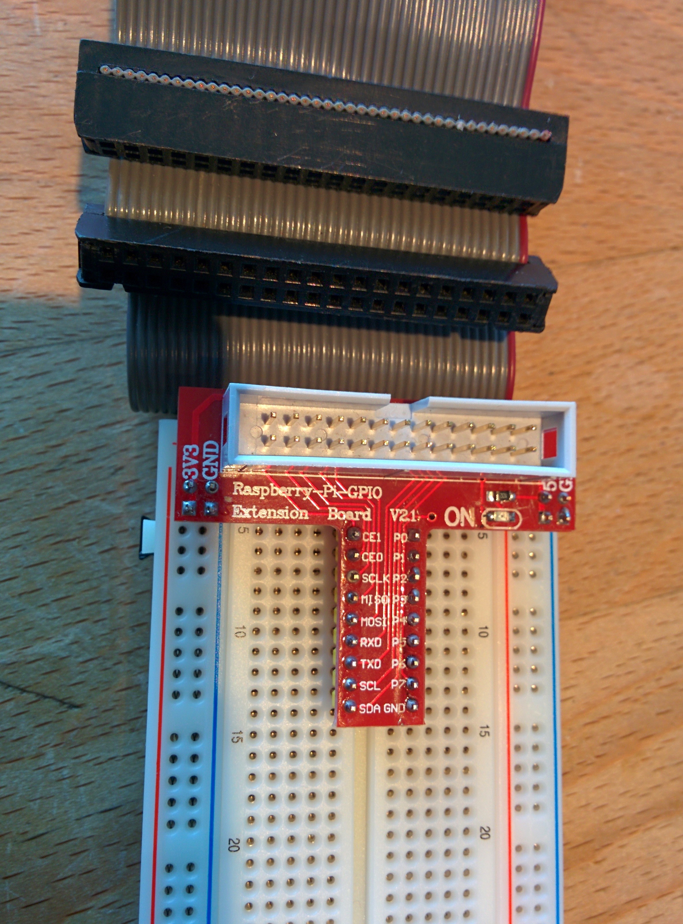
First off it’s easier working if you get the 16 wires you won’t be using out of the. This is easily done using a sharp knife to cut in between cable 26 and 27, thus enabling you to bend that part of the cable away without (on the picture of the breadboard part of the end result you can see that part of the cable is bent away). Then the 26-pin connector can be inserted into the remaining cable, carefully using a screwdriver to make sure that the connecting “knives” go all the way through the wire, thus getting a connection on all wires. Resulting in a cable looking roughly like this:
Measuring the connections
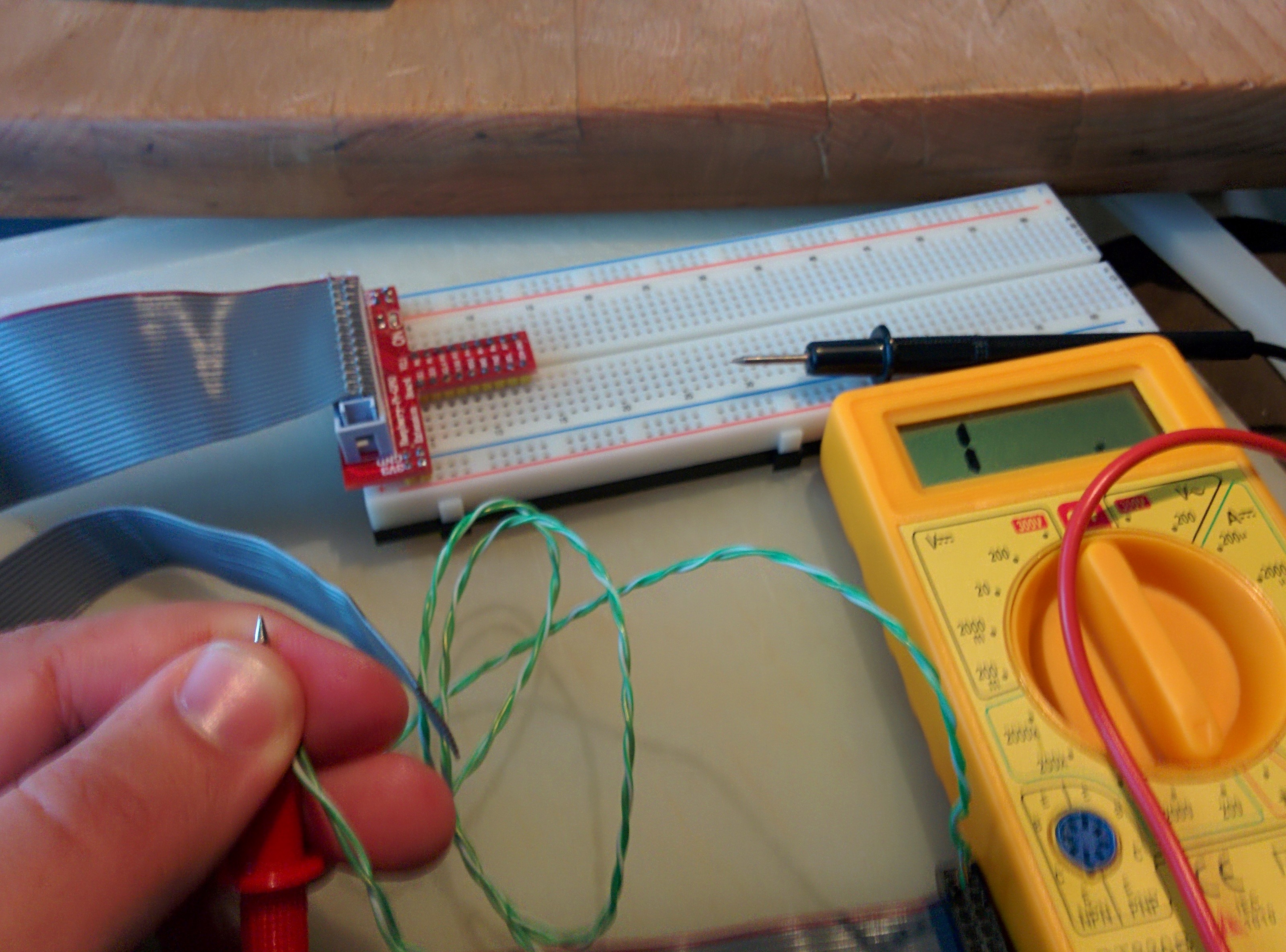
As a paranoid being or sane tester (I wonder which it is), testing that all the pins connect correctly can be done using a multimeter. Simply set it to test for resistance (ohm) and then check every connection. It’s also possible to measure directly on the connector inserted into the breadboard, but in that case be aware that they usually remap them, so the order of the pins isn’t the same.
Using Google revealed that the mapping seem to be quite common. For personal use I created a spread sheet with the mappings. The colored fields are their names on the Raspberry Pi specification, the numbers next to them is the numbers used in the programming interfaces if the pin is referred to by their board numbers and lastly there’s the names used on the connector in the breadboard. In the document there’s also links to the sources A note of warning, this my personal document, and it may be subject to change. Although it’ll most likely not have any regressions in the content, it is still possible, you may want to clone it to your own Google Drive. You’re most welcome to clone the document and do whatever you want with it.
The final result is a cable that connects the 40 pin GPIO of the Raspberry Pi B+ and the breadboard using the simple connector chip. The setup took a fair amount to time to get done and works like a charm.
Comments
Display comments as Linear | Threaded